Modeling Deflection of a Goalie Pole

Leave a comment

I think promises to update regularly are at this point pretty unrealistic. I’ll try more often, but we’ll see what actually happens.

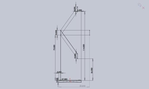
A goalie pole can be approximately modeled as a simple cantilever beam, with the impact of a ball modeled as a point load. To solve for deflection along a beam, one can integrate the moment equation for the beam twice with respect to distance from the support. The case of a cantilevered beam with single point load at the end has already been solved, and the solution is included in essentially any engineering reference text. From this one (PDF warning), deflection at end = (PL^3) / (3EI) . Finding the length is easy enough (I’ll be using 45 inches), as is the Young’s Modulus (E) for any particular material. I is also known; since I will be using round tube the formula is just (pi/12)(r_outer^4 – (r_outer – wall_thickness)^4).

The tricky unknown is P. How much force does a ball impact a goalie pole with? I had to do some sketchy math to come up with an approximate number for this, and it might not be that accurate, but without experimental data there isn’t a ton else I can do. I used impulse-momentum to solve for the impact force. P dt = m v. The mass of a ball is about (2 pounds) / (32.2 ft/s^2) = 0.0621 slug. One of the fastest ball launches I saw this year was from Team 20, who launched a ball at roughly 36 feet per second.

The trickiest part is finding the impulse time (dt). When I was doing the math for this, I was initially expecting to use a polycarbonate tube as the goalie pole. I remembered that at IRI, team 447 had a plastic (PVC?) goalie pole, so I decided to analyze video footage to determine the impulse time. The ball remained in contact with the pole for 2 frames before the pole deflected away from the ball, so let’s say dt is 1/15th of a second.

Now we can solve for the force: F = m v / dt = (.0621 slug) (36 ft / s) / (1/15 s) = ~33.5 lbf. The last variable needed is E. Young’s Modulus for polycarbonate is about 377.1 * 10^3 psi and for aluminum it is about 10.2 * 10^6 psi.

Given these variables, we can write the deflection equation in terms of r for both materials. For polycarbonate of wall thickness .125″, the equation becomes (6 inches) = [(33.5 lb)(45 in)^3]/[3(377.1 * 10^3)(pi/12)(r^4 – (r – .125)^4)] . Using our handy dandy Wolfram Alpha to solve it (I’m pretty lazy), the minimum radius of a polycarbonate goalie pole rigid enough to meet the rules is about 1.57 inches. Unfortunately, 3″ OD polycarbonate is both expensive and too big for the allotted space.

Luckily aluminum gives more promising results. The same equation is used for aluminum, with the bigger Young’s Modulus plugged in. The minimum radius required is r = .5625 inches. This corresponds to a pole of 1-1/8″ OD. I believe a 1″ OD pole would also work just fine, as this is an extreme worst case condition (100% of ball force absorbed by pole, at very tip, from an unusually fast catapult). Hopefully I didn’t make any huge assumptions or math errors; please correct me if I’m wrong!
Raptor SS – Behind the Design – Drivetrain

Leave a comment

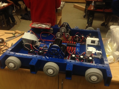
2014 Competition Drivetrain.

2014 Competition Drivetrain.

The 2791 drivetrain has been carefully iterated over the past four years. We began using this style of drivetrain in 2011. A single 9mm HTD belt drove an entire side of the drivetrain, all contained within a 3×1.5 tube. The drive also featured a weird gearbox that finished with a belt reduction. This drivetrain was not issue free. The single belt was not strong enough for what we tried to do. Tensioning the system was extremely difficult. The belt reduction in the gearbox failed, replaced with 25 chain. The drive ratcheted going full forward to full reverse. All in all, a decent start but a long way from competitive. Considering our constraints in 2011, we should have built the kit frame.

Our 2012 drivetrain was a big improvement. Integrated single speed gearboxes laid flat with the profile of the tube. A pair of 15mm belts were used instead of a single 9mm belt. Instead of tensioning, exact center distances were machined. The result was an issue free drivetrain that led us to a Regional Finalist performance. Our 2013 drive was similar, but with a single belt and 4 wheels instead of two belts and 6 wheels. We took a bit of a step backward in 2013 due to some gearbox design problems and the challenges of repairing and iterating a gearbox integrated into the robot, but ultimately the 2013 drive was successful enough for offensive and defensive play.

We planned a few changes for 2014 even before the season began. We moved from an integrated gearbox to a self-contained unit to allow for upgrades, on-bench repairs, and replacement. Counterbores were added for all standoffs to ensure rigidity and help with concentricity between plates. We also switched to exclusively Vex gears for maximum efficiency and ratio flexibility. The result was a very efficient gearbox that could take 3 CIMs as input and output a variety of competitive speed ratios. As Kickoff neared, the design was further improved to match the shape and lightening style presented in the 973 RAMP series.

One preseason change we experimented with was switching to 4″ wheels and 2.5″ tube. We really wanted to use smaller wheels to reduce weight and gearing demands, and our previous year belts could fit inside a smaller tube with some effort. Ultimately we decided against this once the game came out, but it’s an option for the future.

Once the game was released, we began working on the drive train immediately We knew that the game used a fully open, completely flat field. The nature of single game piece, zone play indicated to us that quick acceleration and mobility across medium distances was of the utmost importance. Additionally, defense was clearly going to be a large part of the game and our drive needed be able to play some defense / resist pushing. Given our constraints and experience, we picked a single speed, 6 CIM drive train , geared about 6.1:1. This gave us some ability to push, very quick acceleration, and a top speed of 13 feet per second.

Due to the lack of obstacles in the game, it was decided there was no reason not to use 3″ drive tubes with 4″ wheels. We quickly designed a simple “west coast” style frame for this configuration using exact center distances. The drive was designed to accommodate 4″ wheels, but also to allow 5″ wheels in case of an unforeseen ground clearance issue. Custom gussets designed by students were used to hold it together in addition to a solid belly pan for rigidity. All parts could be CNC milled, except the belly pan which was water jet by RPI. Rivet nuts and hole patterns were placed throughout the structure of the chassis to allow mounting of whatever manipulator we felt necessary. The frame was laid out such that bumper supports would stick out about every 7.75 inches. We have gone back and forth between using a square tube “upper frame” for bumpers and just having supporting members stick out of the frame. This year we decided on these members to facilitate whatever kind of superstructure we ended up with.

The biggest decision to make with the frame was dimensions. Not wanting to compromise our ability to go with any particular design, we designed our frame to be 28×27.5 inches. In retrospect, if we knew we would be using an arm I would have designed a 30×25.5 inch frame instead to allow more room for the manipulator. If we went with this shape and changed our design, however, we would not be able to grab the ball using a 16-style intake.

Ultimately, our drivetrain this season was issue free, efficient, powerful, and generally well done. We had no issues with current draw, as I initially feared, nor were we ever in a situation where we lost a head to head pushing match. About the only change I would make is the addition of some kind of aid to spin out of T-bone pins. In addition, if we knew in advance that we could get a waterjet belly pan, we likely would have used a thicker pan and heavily lightened it.

Raptor SS – Behind The Design – Introduction

Leave a comment

So it’s been a good solid two years since I’ve posted here. Considering I like to pretend anything I said more than six months ago never happened, I was just considering starting a new blog, hiding all the old posts, etc. but I’m too lazy and they could be of value to someone. Oh well.

In any case, I’ve been inspired by my newfound free time and procrastination to work on a series of blog posts about the design of Shaker Robotics’s 2014 robot, Raptor SS. I think it is the best robot we’ve ever fielded and at its prime it was one of the top truss scorers and pickups at our events. It’s got some cool successful features and a few notable design failures. Overall, I’m happy with how our season went and I’m convinced that if we keep this up we’ll be on our way to regional wins in no time.

Raptor SS

Raptor SS, as shipped. A few revisions between this and the final robot.

Currently here’s the plan for posts:

  • Drivetrain
  • Design Strategy
  • Claw / Intake
  • Shooter
  • Arm / Shoulder
  • FLR Iteration

As with any big plan I make, there’s a solid chance I won’t actually follow through and make all these posts, but hopefully starting with this one will help pressure me into finishing these. Any excuse to procrastinate, right?

Kitbot on Steroids – “The Yardstick”

2 Comments

If you’ve ever been on Chief Delphi outside of competition season, the most common post in CD-Media is inevitably a CAD render of a drivetrain. I think it’s pretty great that students, college students, and mentors alike think about how to improve in the offseason, including the buildup of a bit of a “design library”, but often teams get carried away with dreams of custom drivetrains. They do this to the point where they ignore the very good drivetrain right under their noses, or write it off as weak or unstable. I’m referring to the Kitbot on Steroids

In some respects, the Kitbot is a bit incomplete. It comes geared pretty fast and a bit short on rigidity. Team 1114 has stepped in and provided, in painstaking detail, ways to upgrade the Kitbot to what they call the “Kitbot on Steroids“. The main upgrades include a more reasonable free speed, six powered high traction wheels, and a wooden baseplate for added rigidity. All of these together make for a very competitive drivetrain that is fully capable of performing in the upper 25% of FIRST.

But you don’t see many CAD designs that copy the Kitbot on CD. You see a lot of teams that borrow from the elegant and innovative “West Coast Drives” of 254 fame. I’m not going to pretend that my team doesn’t look up to these teams and look for inspiration, and there is a lot of 254 in 2791’s driveline. But I think that helps qualify my point here a little. These teams are copying the best as a starting point, but oftentimes ignore their own resources and limitations in doing so. So I think instead of using the Poofs as a yardstick and a starting point, people should use the Kitbot on Steroids.

Not to say one should start CADing something that looks just like the Kitbot on Steroids and fabricating that! I’m saying that the Kitbot on Steroids should be “the yardstick” – the drivetrain all other designs have to be “better than” to get built.

To make a comparison, you have to start with some design criteria. Here’s a few for the sake of this point:

  • Weight
  • Design Time
  • Fabrication Time
  • “Performance”

The Kitbot on Steroids is a pretty good drivetrain weight wise. According to my calculations (I don’t have one sitting in front of me), with CIMs and without electronics the thing should weigh somewhere around 45 pounds. In terms of design time – none! Fabrication time? One meeting. In terms of performance, the drivetrain is comparable to any high traction six wheel drive.

Compare that to the “Poofs drive”. I have to make some assumptions here to make this point, so forgive the pretense of inside information I don’t have. The Poofs drive weighs a lot less, and performs exceptionally well in terms of sheer efficiency. Their design time, while not “none”, is pretty low due to their experience. Their fabrication time, while not a single meeting, is effectively lowered as much as possible and tuned to their entire team’s resources. The thing to take away from this is that the Poofs take a dramatic weight improvement and helpful performance gains by minimizing the expensive tradeoffs of design and fabrication time.

So how does one apply this lesson to themselves, assuming that one is not a team with the resources to rival teams like the Poofs? Look at the Kitbot on Steroids when evaluating a design. If one can’t beat 45 pounds with a custom skid steer drivetrain, it is all but a waste of time, energy, money, and effort to build something that ISN’T the Kitbot on Steroids. I’d really look at the actual performance advantages a custom drive would give, and honestly evaluate if they are worth the dramatic effort they take.

It’s not THAT hard to design a solid drivetrain that shaves a few pounds off the Kitbot. But to do it in such a way that it gives a competitive advantage in the big picture – that’s a challenge. As I play around in CAD the next few months, you better believe I’ll be using the KoS as my yardstick.

Sabbatical

Leave a comment

So I’ve been pretty hardcore neglecting this blog! I figure I should probably start posting to it again. I’ve been on a bit of a forced leave of absence from 2791 this year. I’ve been in Wisconsin since mid-January for health reasons and have been cheering from home for them, but not really involved in their success. Though, I wasn’t really THAT helpful to begin with…

So here’s where I’ll be posting my various musings about FIRST robotic design once again. I want to keep my “head in the game” so to speak with regards to mechanical design… so content should start appearing here soon. In theory.

Overconstraining and How to Force Good Design

Leave a comment

So this build season’s painfully short hours have, in my opinion, led Shaker to unintentionally stumble into a great design process. The process has essentially been this:

1. Analyze strategy and prioritize.

2. Come up with a concept for each subsystem to match the strategy.

3. Simplify the subsystems.

4. Integrate subsystem design.

5. Simplify the integrated design.

6. Cut out all non-essential features and see if it still works.

7. Repeat steps 4 on until the robot is doable.

This rough process, combined with some lessons from JVN’s excellent design presentation, has served us very well. Eliminating robot design on strategy day made picking and prioritizing quite easy. Egos were put aside and consensus was built – we did strategy and drivetrain selection in 2 hours! Then we come up with ideas… then we cut them down, with never ending revision after revision. This eye to detail and critical attention put on the design as a whole instead of building piece by piece has led to part after part getting simpler and simpler.

I think the key to FIRST design is a lot like weight reduction. Start big, think big picture, make sure your piece does what you want it to, then cut away everything extraneous and non-essential.

Thoughts on the 10 Hour / Week Build Season: Week 1

Leave a comment

So Shaker is working on a unique schedule because of mentor time constraints. As a result, we have 5 meetings a week in 2 hour bursts. This is a lot less time than we’ve had last year and have spent the better part of preseason preparing for this and as a result we’re better off.

The first thing I’ve noticed is that for early design, we are getting as much if not more done than at a longer meeting. 2 hours seems like JUST the right amount of time to really work on concepts and think as a team without getting bored, distracted, or losing interest. I’m sure as the season goes on I’m going to loathe having short meetings where “nothing gets done” – but right now they are the perfect time to work through tough problems.

We try to use the time wisely by doing a lot of the “hard work” outside the meetings and bringing them to the full group to present and discuss. For example, I did a sketch of Shaker’s current four bar arm concept completely at home over about 3-4 hours of work and discussion. This saved time that would be spent at the meeting fighting over it. Then I brought it in and it was presented alongside student concepts that were just as refined if not more so at home. If we can keep this up for CAD design and robot building, we will have a smooth season.

2791 Nonteaser

1 Comment

lol

Scoring Calculator

Leave a comment

This has been by far the most helpful tool ever for my team and me.

http://www.chiefdelphi.com/forums/showthread.php?t=88417

It is a great way to calculate rack scores and otherwise figure out where ideal places to score are. Thanks 103!


Oh yeah, here’s a design sketch.

It's a little old, the numbers have been adjusted a bit.

Kickoff

Leave a comment

My Kickoff is really weird this year. Traditionally I wake up at 6 AM, drive across the state of Wisconsin, then meet up with 1714 and eat Krispy Kremes waiting to go and sit in front of the big projectors at the Wisconsin Remote Kickoff.

This year, I rolled out of my bed in New York (or rather, the friend I’m staying at’s bed) and checked if we got NASA TV on cable. We don’t. Streaming it I guess.

Later today I’ll spend a few hours on the phone with 3450, then roll out to Shaker’s Kickoff meeting, now delayed until 4 PM due to weather. I suspect I’ll probably get a call from a team member before then.

Older Entries